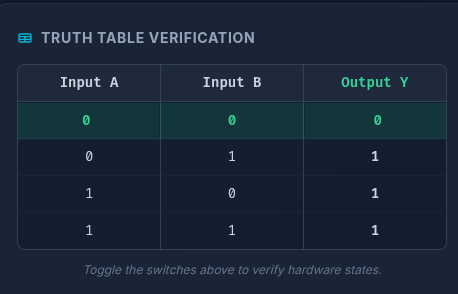
OR Gate
Dataflow
----------------------------------------------------------------------------------
-- Company:
-- Engineer:
--
-- Create Date:    11:06:11 04/03/2026
-- Design Name:
-- Module Name:    OR_GATE_MODULE - Behavioral
-- Project Name:
-- Target Devices:
-- Tool versions:
-- Description:
--
-- Dependencies:
--
-- Revision:
-- Revision 0.01 - File Created
-- Additional Comments:
--
-------------------------------------------------------------------------------------S
library IEEE;                 -- Import the standard IEEE library for electronic design
use IEEE.STD_LOGIC_1164.ALL;  -- Use standard 1164 package for STD_LOGIC types (0, 1, Z, etc.)

entity OR_Gate is         -- Define the physical 'black box' interface of the module
    Port (                    -- Declare the input and output pins (ports)
           A : in  STD_LOGIC;

           B : in  STD_LOGIC;

           Y : out STD_LOGIC
    );
end OR_Gate;              -- Close the entity definition

architecture Dataflow of OR_Gate is  -- Begin the architecture definition named 'Dataflow'
begin                                    -- Start the execution block of the architecture
    -- Concurrent Signal Assignment: Evaluates continuously, acting like a physical wire
    Y <= A or B;                     -- Assign the result of the logic directly to output Y
end Dataflow;                            -- Close the architecture block
Testbench
--------------------------------------------------------------------------------
-- Company:
-- Engineer:
--
-- Create Date:   11:07:57 04/03/2026
-- Design Name:
-- Module Name:   /home/student/Desktop/13000224121/OR_GATE_PROJECT/or_gate_tb.vhd
-- Project Name:  OR_GATE_PROJECT
-- Target Device:
-- Tool versions:
-- Description:
--
-- VHDL Test Bench Created by ISE for module: OR_Gate
--
-- Dependencies:
--
-- Revision:
-- Revision 0.01 - File Created
-- Additional Comments:
--
-- Notes:
-- This testbench has been automatically generated using types std_logic and
-- std_logic_vector for the ports of the unit under test.  Xilinx recommends
-- that these types always be used for the top-level I/O of a design in order
-- to guarantee that the testbench will bind correctly to the post-implementation
-- simulation model.
--------------------------------------------------------------------------------

library IEEE;                 -- Import the standard IEEE library for electronic design
use IEEE.STD_LOGIC_1164.ALL;  -- Use standard 1164 package for STD_LOGIC types (0, 1, Z, etc.)

ENTITY tb_OR_Gate IS                  -- Define an empty entity for the testbench (no external pins)
END tb_OR_Gate;                       -- Close the testbench entity

ARCHITECTURE behavior OF tb_OR_Gate IS -- Begin the testbench architecture
    -- Unit Under Test (UUT) Declaration
    COMPONENT OR_Gate                 -- Declare the module we want to test
    PORT(                             -- Define the pins matching our module
           A : in  STD_LOGIC;
           B : in  STD_LOGIC;
           Y : out STD_LOGIC
    );
    END COMPONENT;

    -- Input Signals (Registers to hold state)
    signal A : std_logic := '0';      -- Initialize input signal A to LOW ('0')
    signal B : std_logic := '0';      -- Initialize input signal B to LOW ('0')
    -- Output Signals (Wires to read state)
    signal Y : std_logic;             -- Signal to capture the output Y

BEGIN                                 -- Start the testbench execution
    -- Instantiate the Unit Under Test (UUT)
    uut: OR_Gate PORT MAP (           -- Create an instance of our gate module
        A => A,                       -- Connect testbench signal A to UUT pin A
        B => B,                       -- Connect testbench signal B to UUT pin B
        Y => Y                        -- Connect UUT pin Y to testbench signal Y
    );

    -- Stimulus process: Generates artificial timing signals
    stim_proc: process
    begin
        wait for 20 ns;               -- Initial stabilization delay (wait 20 nanoseconds)

        A <= '0'; B <= '0'; wait for 100 ns; -- Apply inputs 0,0 and advance time by 20ns
        A <= '0'; B <= '1'; wait for 100 ns; -- Apply inputs 0,1 and advance time by 20ns
        A <= '1'; B <= '0'; wait for 100 ns; -- Apply inputs 1,0 and advance time by 20ns
        A <= '1'; B <= '1'; wait for 100 ns; -- Apply inputs 1,1 and advance time by 20ns
        wait;                         -- Suspend simulation permanently
    end process;                      -- End the stimulus process
END;                                  -- Close the testbench architecture